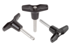
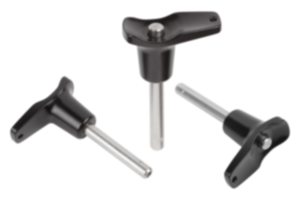
Material
Grip and push button thermoplastic.
Metal parts stainless steel.
Metal parts stainless steel.
Version
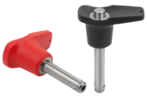
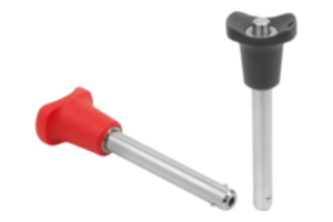
Grip black.
Push button traffic red.
Steel parts bright.
Push button traffic red.
Steel parts bright.
Show more
Show less
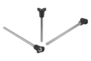
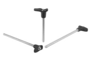
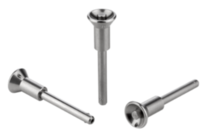
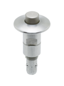
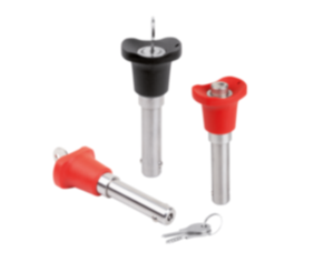
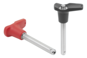
Ball lock pins with plastic grip and metal collar
from
€13.71
plus sales tax
plus shipping costs
Ball lock pins with plastic grip and plastic collar
from
€11.33
plus sales tax
plus shipping costs
Description
Material
Grip and push button thermoplastic.
Metal parts stainless steel.
Metal parts stainless steel.
Version
Grip black.
Push button traffic red.
Steel parts bright.
Push button traffic red.
Steel parts bright.
Note
Ball lock pins are used for easy fastening or joining of components or workpieces.
The two balls are disengaged by pressing the push button and the pin can be slipped into holes in the workpieces. Release the button to lock the balls and secure the connection.
Form A is suitable for applications where high demands and precision are required.
Shear force double shear (F) = S · τ aB max.
The values given for the shear force are the theoretical breaking load.
These are non-binding reference values without consideration of safety factors and exclude any liability. The values given are for information purposes only and do not constitute a legally binding assurance of properties.
The load values have been calculated in accordance with DIN 50141. Each user must determine individually whether the ball lock pin is suitable for the respective application.
Different materials in which the ball lock pins are used, weather conditions and wear can influence the determined values.
Features
Form A:
Pin ground, metal collar, high axial pull-out force
Form B:
Pin h9, plastic collar, low axial pull-out force
Pin ground, metal collar, high axial pull-out force
Form B:
Pin h9, plastic collar, low axial pull-out force
Drawing reference
1) Metal collar
2) Plastic collar
2) Plastic collar
Accessory
Bushes for ball lock pins K0724
Safety spiral cable K0367
Retaining cable with loop K0367
Key ring K0367
Safety spiral cable K0367
Retaining cable with loop K0367
Key ring K0367


